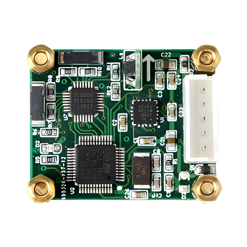
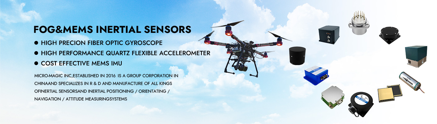
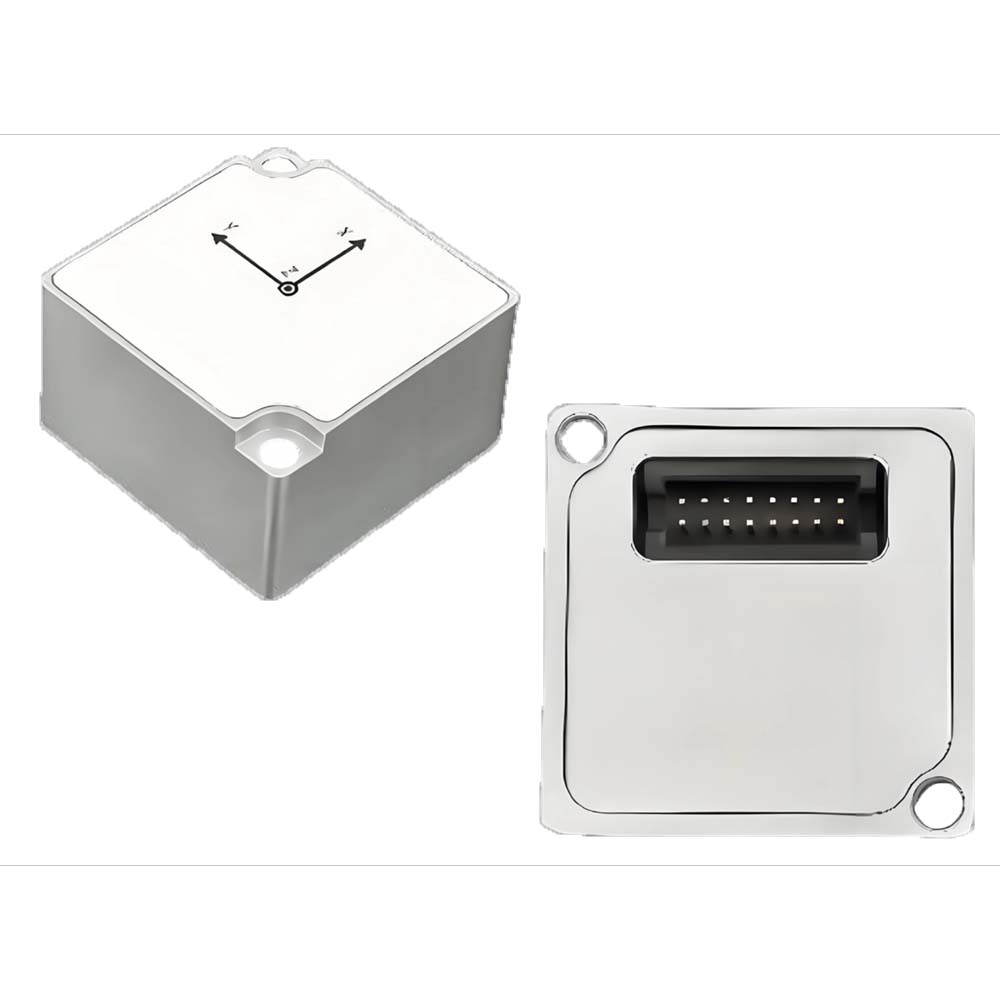
Sensor MEMS IMU AHRS de grado táctico de alta precisión U4200 para navegación de robots UAV
La serie U4200 es un sensor IMU/VRU/AHRS compuesto por una IMU MEMS de grado táctico y un magnetómetro. Incorpora un filtro de Kalman extendido adaptativo de desarrollo propio, un algoritmo de análisis dinámico del ruido de la IMU y un algoritmo de análisis del estado de movimiento de la portadora, lo que permite obtener ángulos de actitud precisos en condiciones de alta dinámica y reducir la deriva de los ángulos de rumbo.
Cada sensor se somete a una compensación precisa antes de salir de fábrica, que incluye la temperatura, el sesgo cero, el factor de escala y el eje transversal.
Los sensores de la serie U4200 transmiten datos a través de diversas interfaces como RS232, RS422 y CAN, y ofrecen una amplia gama de configuraciones de usuario.
La serie U4200 se puede sincronizar con el sistema mediante activación externa y también puede lograr la alineación temporal con sistemas externos como radares y cámaras a través de la función de salida síncrona.
La interfaz gráfica de usuario (GUI) multifuncional permite evaluar rápidamente el producto, y sus funciones incluyen, entre otras, la configuración de módulos, la visualización de datos, la actualización del firmware, el registro de datos, etc.
Número de pieza, :
U4200Pedido (MOQ) :
1Series de productos y parámetros
| Precisión de actitud | Condición | U4200-A | U4200-B | Unidad |
| Cabeceo (±90°) / Balanceo (±180°) (estático) | 0,05 (nominal), 0,07 (máx.) | ° | ||
| Cabeceo (±90°) / Balanceo (±180°) (dinámico) | 0,05 (nominal) 0,07 (máx.) | |||
| Deriva estática de guiñada (±180°) 2 horas (6 grados de libertad) ① | 0.1 | |||
| Asistencia magnética (AHRS) ② | 2 (nominal), 3 (máximo) | |||
| Error de rotación de guiñada (6 grados de libertad) (rotación inferior a 100°/s) ③ | <0,5 (nominal), 1 (máximo) | |||
| Nota: ① El módulo debe permanecer en posición horizontal durante 2 horas. ② Después de la calibración geomagnética, el producto debe configurarse en modo AHRS cuando no haya interferencia de campo magnético en el área circundante. ③ La plataforma giratoria rota continuamente durante 10 vueltas y el ángulo de rumbo acumula error. |
||||
| Giroscopio | Condición | U4200-A | U4200-B | Unidad |
| Rango de medición | ±300 | °/s | ||
| Resolución | 16 | poco | ||
| Error lineal① | 300°/s -40℃-110℃ | ±0,15 (nominal), ±0,3 (máx.) | °/s | |
| 100°/s -40℃-110℃ | ±0,01 (nominal), ±0,04 (máx.) | |||
| error transversal | ±0,15 | % | ||
| Ancho de banda de 3 dB | 235 (nominal), 250 (máx.) | Hz | ||
| Frecuencia de muestreo | 1000 | Hz | ||
| Densidad de ruido | XY: 0,0004 Z: 0,0006 |
°/s/√Hz | ||
| Inestabilidad de polarización cero② | Allan, 1σ | 0,3 | °/h | |
| Estabilidad de polarización cero | 10s, 1σ | 0,5 | °/h | |
| Repetibilidad de sesgo cero | 1σ | 0,8 | °/h | |
| Paseo aleatorio angular③ | Allan 1σ | XY: 0,015 Z: 0,025 |
°/√h | |
| Polarización cero a temperatura completa | -40-85℃ | XY: 0,25 Z: 0,03 |
°/s | |
| Sensibilidad del acelerómetro (en los 3 ejes) | Para una entrada de gravedad constante | 0,00075 | °/s/g | |
| Notas: ①: El error lineal es la desviación máxima en un rango específico con respecto a la línea de mejor ajuste determinada por los valores medidos. El modelo lineal de mejor ajuste utiliza el método de mínimos cuadrados para el ajuste lineal. ②: El valor obtenido al dividir el valor mínimo de la varianza de Allan por 0,664. Durante la medición, se utiliza un filtro de paso bajo de 13 Hz y una frecuencia de muestreo de 200 Hz, y debe haber un tiempo de estabilización de 15 minutos antes de comenzar la recopilación de datos para garantizar una estabilidad térmica completa. ③: El paseo aleatorio angular es un término de ruido blanco estimado a partir de la desviación de Allan en una constante de tiempo τ = 1 segundo. |
||||
| Acelerómetro | Condición | U4200-A | U4200-B | Unidad |
| Rango de medición | 16 | g | ||
| Resolución | 16 | poco | ||
| sesgo cero | 2 | mg | ||
| Error lineal① | 300°/s -40℃-110℃ | ±3 (nominal), ±15 (máx.) | mg | |
| 100°/s -40℃-110℃ | ±0,5 (nominal), ±1 (máx.) | |||
| error transversal | ±0,15 | % | ||
| Ancho de banda de 3 dB | 210 (nominal), 235 (máx.) | Hz | ||
| Frecuencia de muestreo | 1000 | Hz | ||
| Densidad de ruido | 0,0008 | m/s2√Hz | ||
| Inestabilidad de polarización cero② | Allan, 1σ | 10 | ug | |
| Estabilidad de polarización cero | 10s, 1σ | 30 | ug | |
| Repetibilidad de sesgo cero | 1σ | 40 | ug | |
| Paseo aleatorio angular③ | Allan 1σ | 0,03 | m/s/√h | |
| Polarización cero a temperatura completa | -40-85℃ | 0,5 (nominal), 2 (máximo) | mg | |
| Notas: ①: El error lineal es la desviación máxima en un rango específico con respecto a la línea de mejor ajuste determinada por los valores medidos. El modelo lineal de mejor ajuste utiliza el método de mínimos cuadrados para el ajuste lineal. ②: El valor obtenido al dividir el valor mínimo de la varianza de Allan por 0,664. Durante la medición, se utiliza un filtro de paso bajo de 13 Hz y una frecuencia de muestreo de 200 Hz, y debe haber un tiempo de estabilización de 15 minutos antes de comenzar la recopilación de datos para garantizar una estabilidad térmica completa. ③: El paseo aleatorio angular es un término de ruido blanco estimado a partir de la desviación de Allan en una constante de tiempo τ = 1 segundo. |
||||
| Magnetómetro | Condición | U4200-A | U4200-B | Unidad |
| Rango | ±20 | Gauss | ||
| Frecuencia de muestreo | 200 | HZ | ||
| Linealidad (Mejor ajuste de la línea recta: Fs=2G) | 0.1 | Fs% | ||
| Sensor de temperatura | Condición | U4200-A | U4200-B | Unidad |
| Rango | -40 ~ +85 | ℃ | ||
| Error de desplazamiento | ±1 | K | ||
| Mecánica/Medio ambiente | U4200-A / U4200-B | Unidad | ||
| Fuente de alimentación | 4.8 ~ 36 | V | ||
| Consumo de energía | 400 | mW | ||
| Temperatura de funcionamiento | -125 | ℃ | ||
| Hora de inicio① | 2 | s | ||
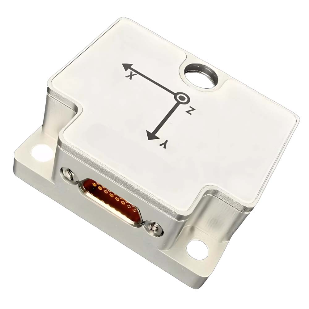
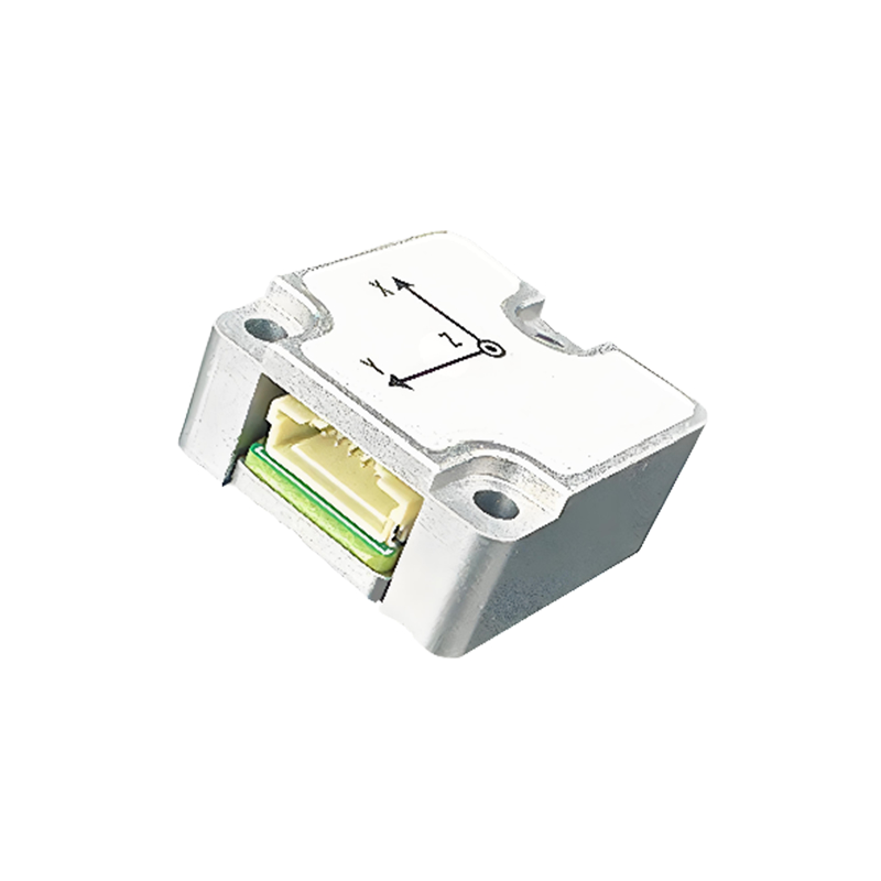
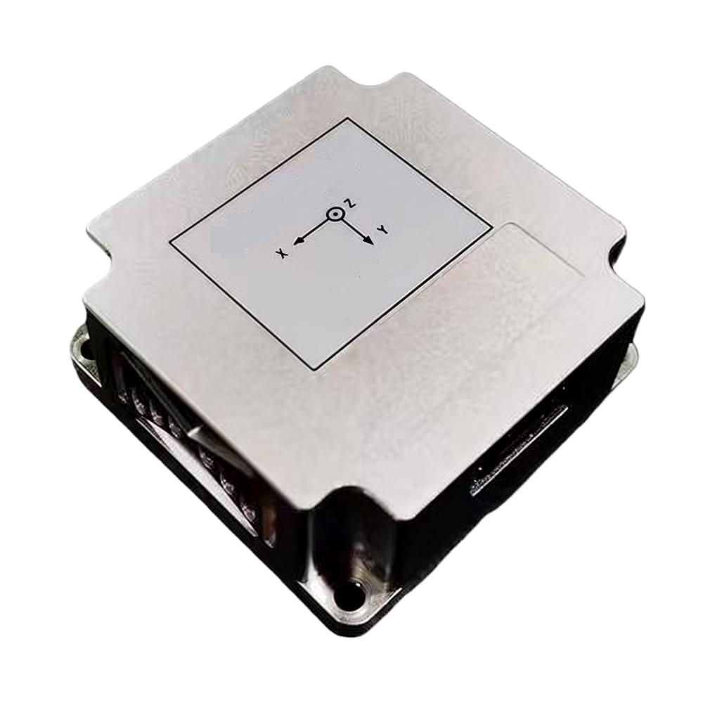
| Tamaño | 44,8*38,6*18,5 | mm | ||
| Peso | 55 | g | ||
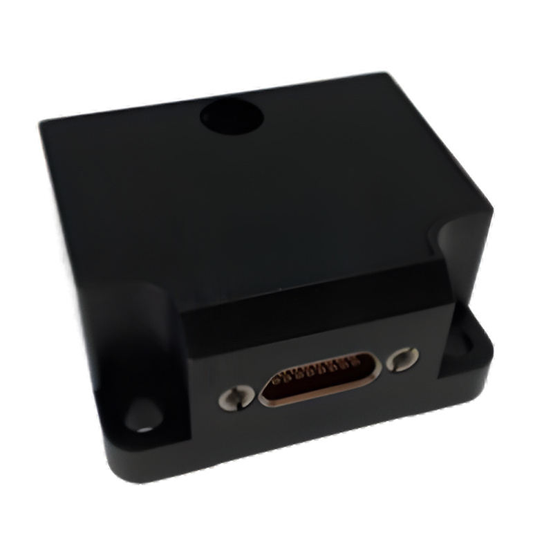
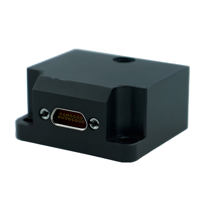
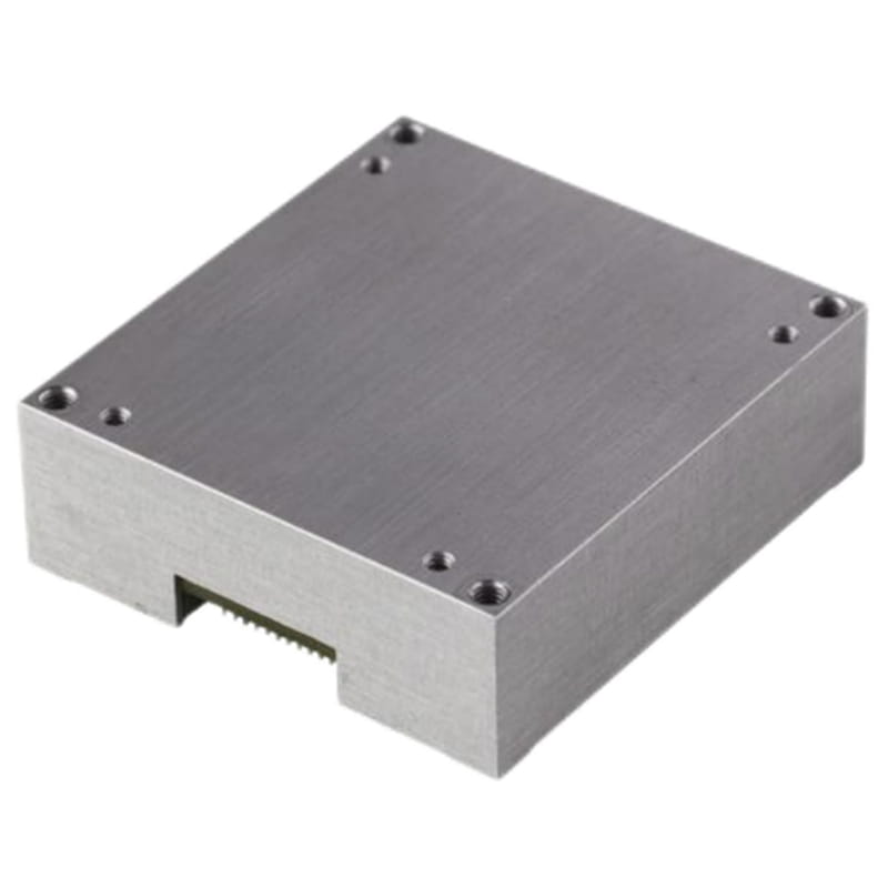
| Material y proceso de la carcasa | Aleación de aluminio CNC | |||
| Tornillos de montaje | M3 | |||
| Antivibración | 1,0 mm (10 Hz-58 Hz) y ≤20 g (58 Hz-600 Hz) | |||
| Choque (duración) <1 ms) | 2000 | g | ||
| Grado IP | IP68 Resistente al agua | |||
| Prueba de caída | Caída libre 3 veces sobre una plataforma experimental de 75 cm de altura. | |||
| choque térmico | Elevar la temperatura de -40 a 85 ℃ en 1 hora, 5 veces. | |||
| Notas: ① El tiempo de arranque se refiere al tiempo que tarda el sistema en apagarse y generar datos válidos. Durante este período, el módulo debe permanecer inmóvil. |
||||
| Interfaz | Parámetros | Condición | Min | Normal | Máximo | Unidad |
| RS232 | Velocidad de transmisión① | 9600 | 115200 | 921600 | latidos por segundo | |
| Partes iniciales | 1 | poco | ||||
| longitud de los datos | 8 | bits | ||||
| Bit de parada | 1 | poco | ||||
| Suma de verificación | Ninguno | poco | ||||
| Velocidad de fotogramas de salida② | 0 | 100 | 1000 | Hz | ||
| impedancia de entrada | RS-232 | 3 | 5 | 7 | kΩ | |
| impedancia de salida | 300 | 10M | Ω | |||
| PODER | Velocidad de transmisión③ | 125 | 500 | 1000 | kbps | |
| Velocidad de fotogramas de salida④ | 5 | 100 | 200 | Hz | ||
| Impedancia de entrada⑤ | con una resistencia de 120 Ω | 120 | Ω | |||
| sin resistencia de 120 Ω | 19 | 30 | 52 | kΩ | ||
| RS422 | Velocidad de transmisión | 9600 | 115200 | 921600 | latidos por segundo | |
| Partes iniciales | 1 | poco | ||||
| longitud de los datos | 8 | bits | ||||
| Bit de parada | 1 | poco | ||||
| Suma de verificación | Ninguno | poco | ||||
| Velocidad de fotogramas de salida | 0 | 100 | Hz | |||
| Impedancia de entrada⑤ | con una resistencia de 120 Ω | 120 | Ω | |||
| sin resistencia de 120 Ω | 48 | kΩ | ||||
| Pasador del gatillo | Voltaje lógico⑥ | Alto | 2 | V | ||
| Bajo | 0,6 | V | ||||
| Demora | Desde el disparador hasta la transmisión de datos | 800 | us | |||
| Notas: ① Si se requieren modificaciones, consulte el manual de instrucciones y programación. ② El sensor admite salida de datos a 1, 5, 10, 50, 200, 250, 500 y 1000 Hz. ③ Si se requieren modificaciones, consulte el manual de instrucciones y programación. ④ El sensor admite salida de datos de 5, 10, 50, 100 y 200 Hz. ⑤ Por defecto, no hay ninguna resistencia de 120 Ω conectada. ⑥ Consulte el capítulo sobre la función de sincronización y el manual de instrucciones y programación para la configuración y el momento de activación. |
||||||
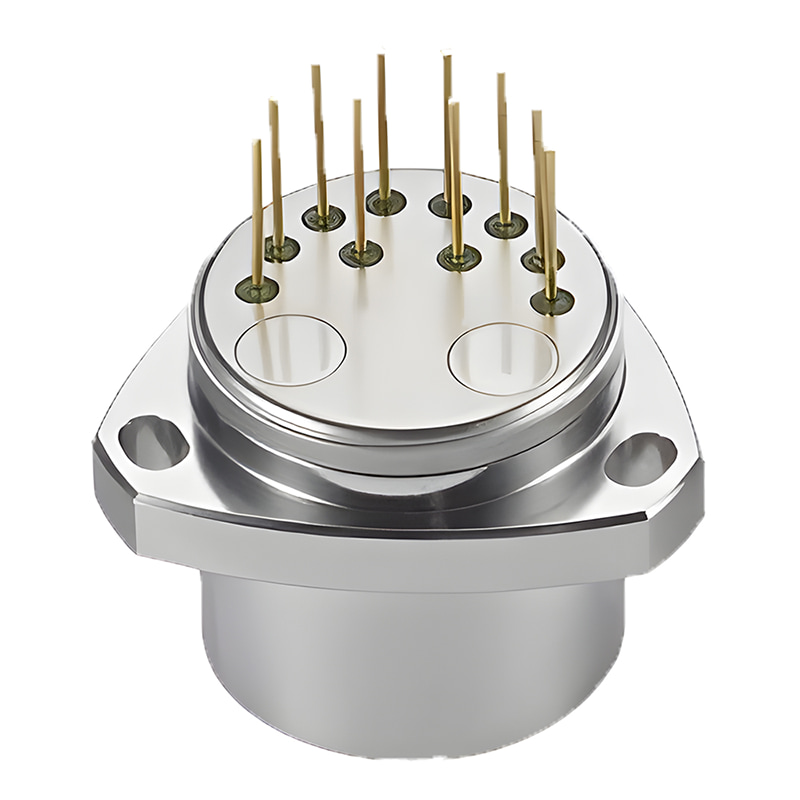
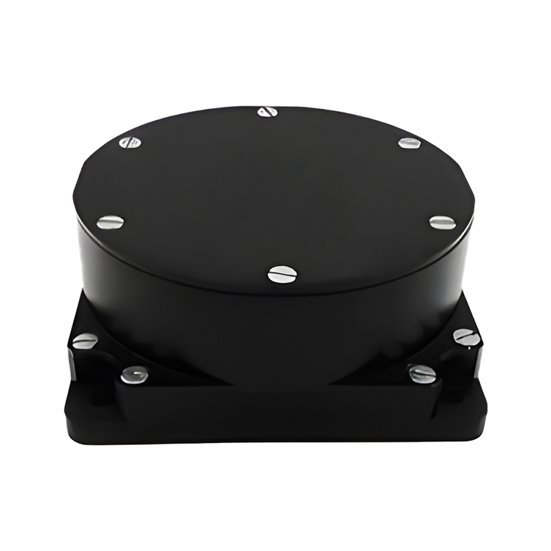
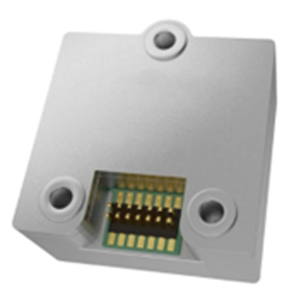
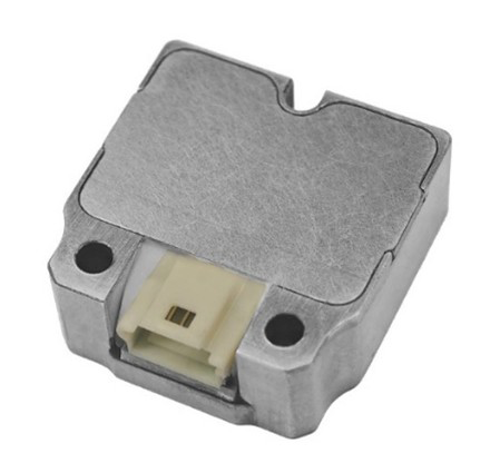
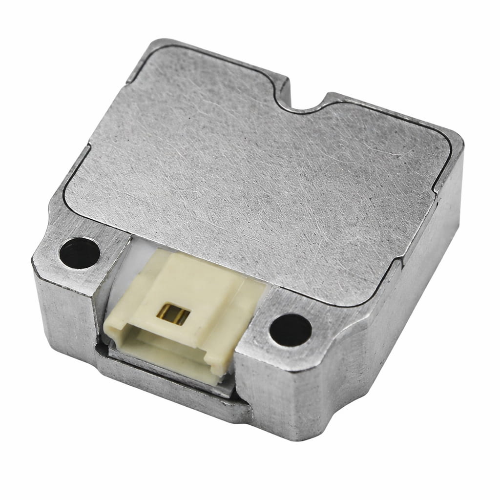
proceso de producción
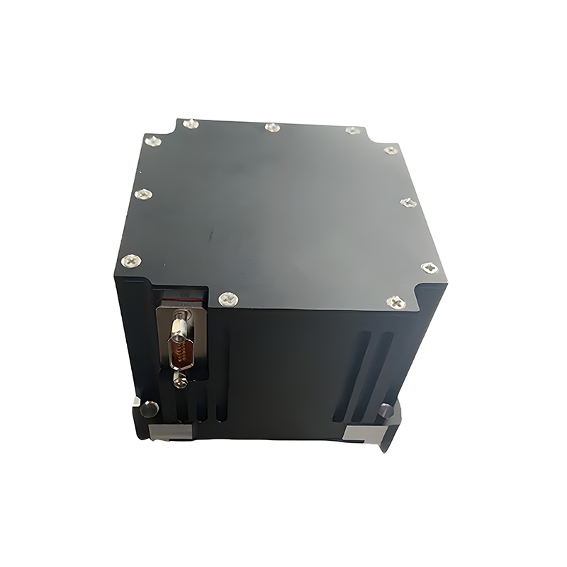
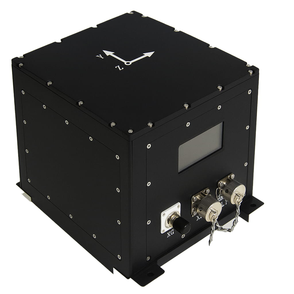
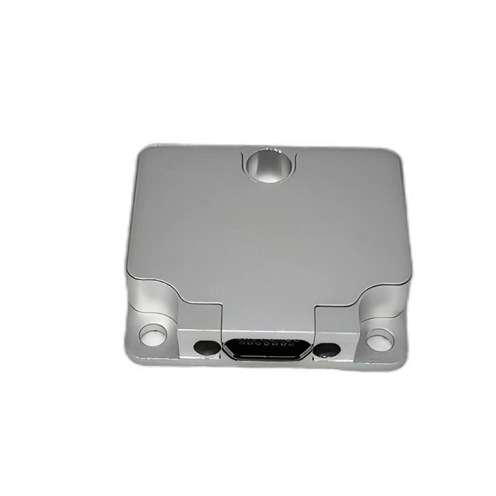
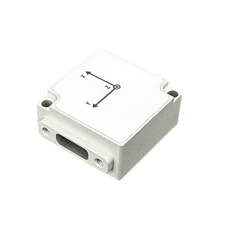
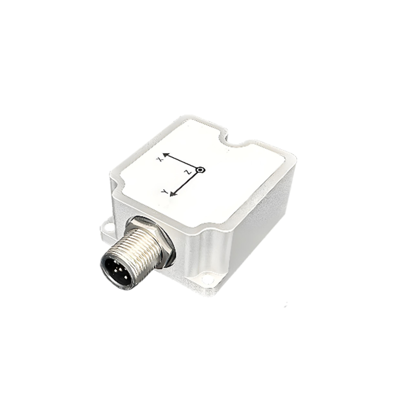
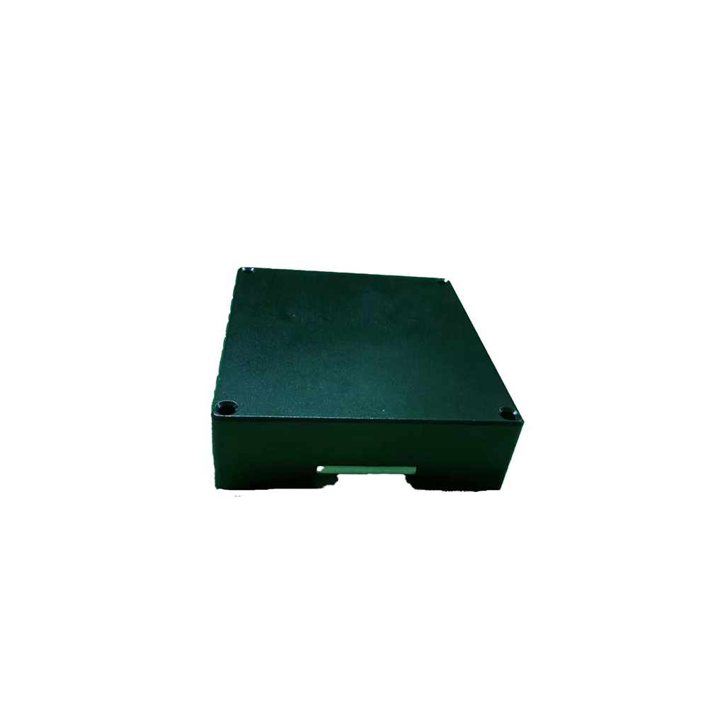
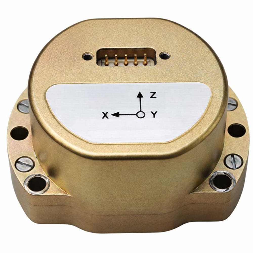
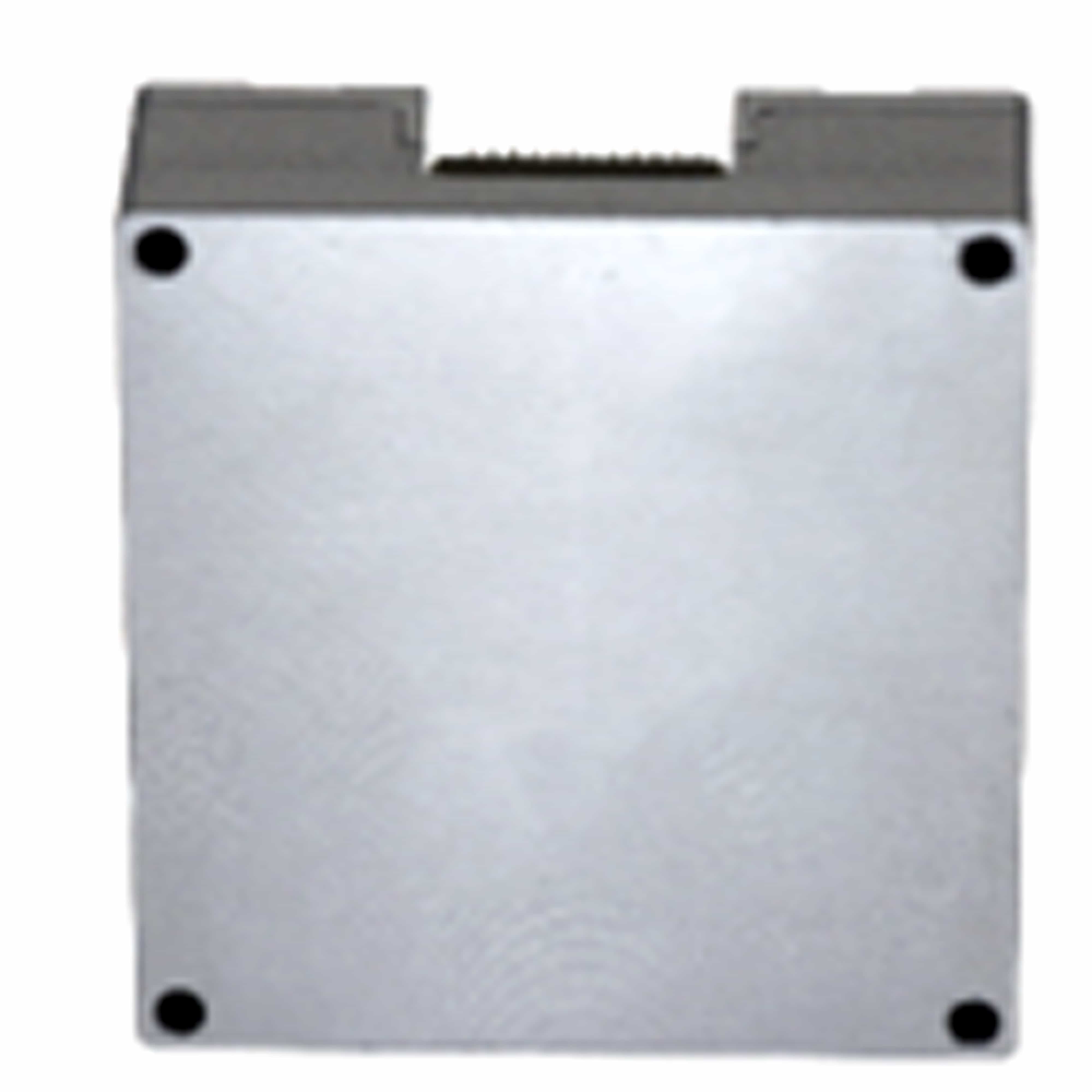
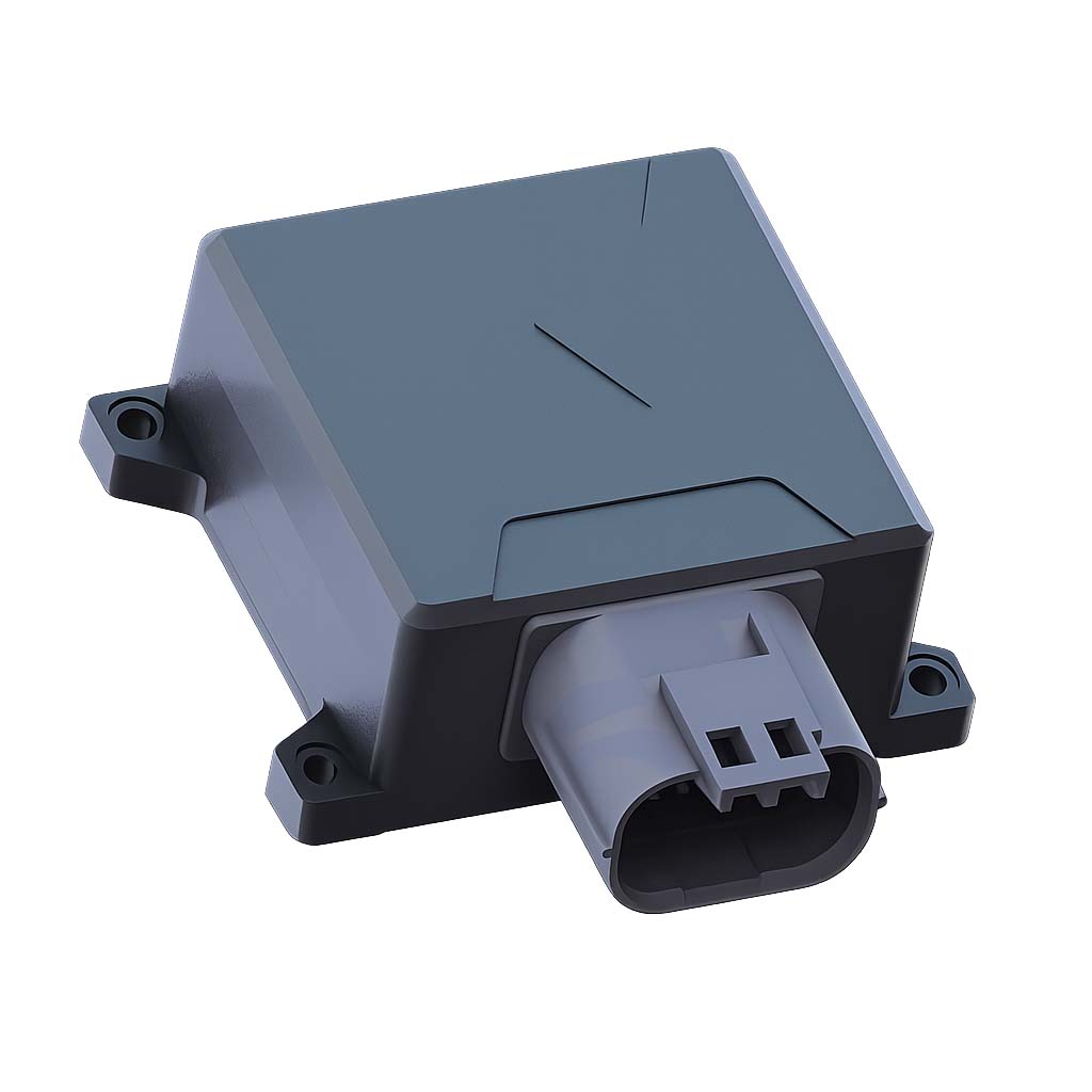
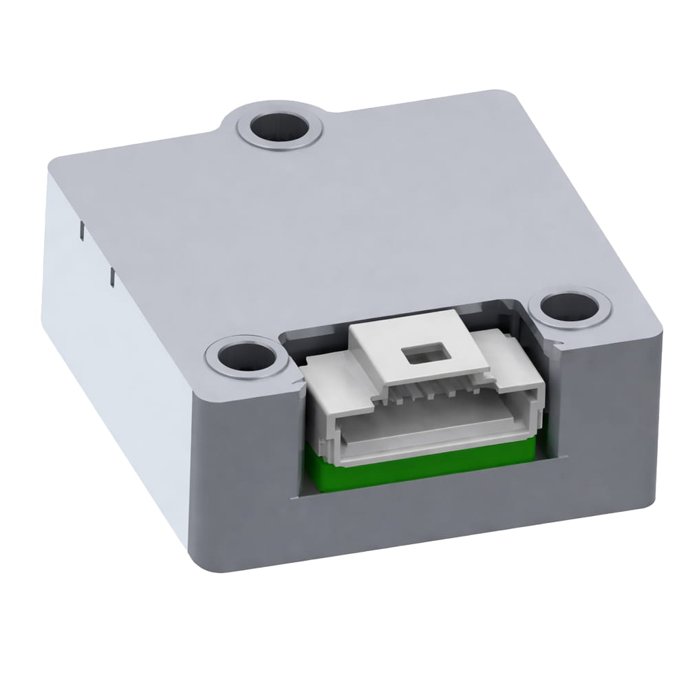
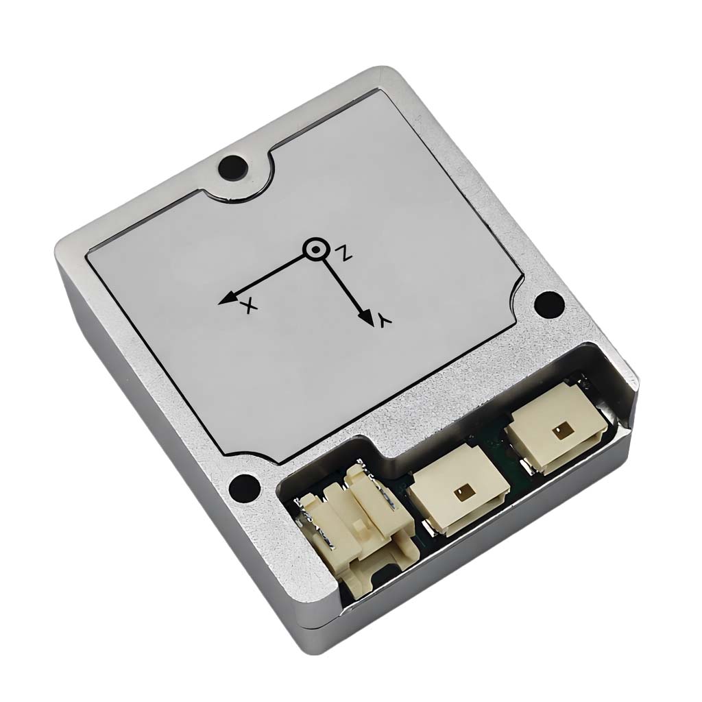
Dimensiones del producto

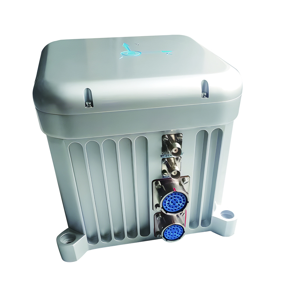
Escenarios de aplicación


Preguntas frecuentes
P1. ¿Para qué se utiliza el U4200?
El U4200 es un sensor MEMS IMU/VRU/AHRS de alta precisión diseñado para referencia de actitud, control de trayectoria, estabilización de plataformas, instrumentos subterráneos, robots no tripulados de baja velocidad, instrumentos de precisión y maquinaria de construcción.
P2. ¿Qué interfaces admite el U4200?
El U4200 admite interfaces de comunicación RS232, RS422 y CAN, con amplias opciones de configuración para el usuario que permiten diferentes integraciones de sistemas.
P3. ¿Qué protocolos de comunicación están disponibles?
El sensor admite múltiples protocolos, incluidos el protocolo binario, CANopen, Modbus, y la interfaz CAN también admite J1939.

Xml política de privacidad blog Mapa del sitio
Derechos de autor @ Micro-Magic Inc Reservados todos los derechos.
 RED COMPATIBLE


 Español