

Introduction
In high-precision inertial navigation and attitude measurement systems, sensor measurement accuracy directly constrains the system's overall performance. In practical engineering applications, non-orthogonal mounting errors and nonlinear scale errors are the two primary factors affecting measurement accuracy. Non-orthogonal mounting errors arise from the inability to achieve ideal orthogonal mounting of the tri-axial sensors on the carrier, resulting in inter-axis coupling and crosstalk; nonlinear scale errors manifest as a nonlinear relationship between sensor output and input, a phenomenon particularly pronounced in extreme temperature environments. These two types of errors are coupled; if not properly addressed, they can severely degrade the accuracy of the navigation solution.
Modeling and Compensation of Non-orthogonal Mounting Errors
Error Mechanism and Mathematical Model
The essence of non-orthogonal mounting error lies in the deviation between the sensor's actual sensitive axes and the ideal instrument coordinate system. Taking a tri-axial accelerometer as an example, let OXYZ denote the ideal coordinate system and OX′Y′Z′ denote the coordinate system of the actual sensitive axes; the relationship between them can be described by a 3×3 mounting error matrix.
To precisely characterize this error, three independent error angles for each actual axis relative to the ideal orientation are defined as follows:
 (Azimuth error): The angle between the projection of the i-th actual sensitive axis onto the horizontal plane and the direction of the ideal coordinate axis.
 (Tilt error): The pitch/tilt angle of the i-th actual sensitive axis relative to the ideal horizontal plane.
 (Torsion error): The rotation angle of the i-th actual sensitive axis about its own axis.
Here, the subscript 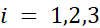 corresponds to the X, Y, and Z axes, respectively. Based on these definitions, the transformation relationship between the actual sensitive axes and the ideal axes can be represented by a rotation matrix R, and the attitude measurement output equation is:
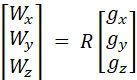
The rotation matrix R is:

The specific meanings of the elements in the matrix are described as follows:
Row 1 (corresponding to the actual X-axis output):  represent the azimuth angle error, tilt angle error, and torsion angle error of the X-axis, respectively.
Row 2 (corresponding to the actual Y-axis output):  represent the azimuth angle error, tilt angle error, and torsion angle error of the Y-axis, respectively.
Row 3 (corresponding to the actual Z-axis output):
Escanea y envíalo a WeChat. :