En el uso real del bus CAN, como se muestra en la Figura 1, se debe conectar una resistencia de 120 Ω en ambos extremos del bus. Entonces, ¿cuál es la base para usar una resistencia de 120 Ω?
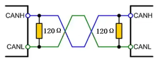
Figura 1
A continuación tomamos el diagrama de arquitectura interna de TJA1044 como ejemplo para el análisis.

Figura 2
La característica del bus CAN es que el dominante representa 0 y el recesivo representa 1. Cuando el bus es recesivo, los transistores superior e inferior Q1 y Q2 del TJA1044 se desactivan, dejando CANH y CANL inactivos con una diferencia de voltaje de 0 V. Cuando el bus es dominante, los transistores superior e inferior Q1 y Q2 del TJA1044 se activan, creando una diferencia de voltaje entre CANH y CANL. Si no hay carga en el bus y el bus es recesivo, la resistencia diferencial del bus será muy grande, lo que provocará que incluso una mínima energía externa lo convierta en dominante. Esto se debe principalmente a que el voltaje umbral mínimo para dominante en los transceptores típicos es de tan solo unos 500 mV. Por lo tanto, para mejorar la inmunidad del bus a las interferencias, se requiere una resistencia de terminación. Sin embargo, esta resistencia debe mantenerse lo más baja posible (y también para evitar una corriente excesiva).
Además, también debe considerarse la capacitancia parásita en el bus. Cuando el bus es dominante, el capacitor se carga, y cuando es recesivo, se descarga. Si el bus no tiene resistencias en paralelo, solo puede descargarse a través de los transceptores en ambos extremos. Esto afecta el tiempo de transición entre los dos estados (recesivo y dominante), lo que resulta en anomalías en la forma de onda (ascenso), como se muestra en la Figura 3. Cuando una señal encuentra una discontinuidad de impedancia en una ruta de transmisión de alta velocidad, causa reflexiones de señal, que llamamos discontinuidades de impedancia. Agregar resistencias terminales puede eliminar o reducir el impacto de estas reflexiones de señal. Las resistencias terminales absorben la energía de la señal, evitando que se disperse en el bus. Entonces, ¿por qué 120 Ω? De hecho, la norma ISO 11898-2 define claramente 120 Ω como el valor de resistencia más razonable, determinado mediante extensas pruebas experimentales.
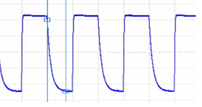 Figura 3
Si desea verificar qué tan grande es la resistencia terminal del bus requerida en un proyecto real, puede probarlo utilizando el método que se muestra en la Figura 4 a continuación.
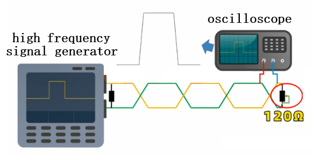 Figura 4
Conecte una resistencia ajustable en paralelo al bus y ajústela hasta que la forma de onda cuadrada permanezca sin distorsión. Al seleccionar la potencia de la resistencia terminal, se debe tener en cuenta la condición de cortocircuito de la interfaz. Esto significa que, en caso de cortocircuito, la corriente fluirá directamente de CANH a CANL. Sin embargo, la corriente que un transceptor CAN típico puede soportar es de tan solo decenas de mA (debido a las medidas internas de limitación de corriente del transceptor). Por ejemplo, el TJA1044 solo maneja 50 mA. Basándonos en P = I² * R, obtenemos 50 mA * 50 mA * 120 Ω = 0,3 W. Por lo tanto, la potencia de la resistencia se selecciona en 0,25 W, que es el encapsulado 1206 común.

Xml política de privacidad blog Mapa del sitio
Derechos de autor @ Micro-Magic Inc Reservados todos los derechos.
 RED COMPATIBLE


 Español